FBR Burner Maintenance & Troubleshooting Guide
Maintain optimal FBR burner performance with systematic maintenance intervals and diagnostic procedures for gas, diesel, and heavy-oil models. 3G Electric Indonesia provides localized support with IDR invoicing and delivery to Jakarta, Surabaya, and Bandung within 6–10 business days, including Bea Cukai customs clearance (typically 3–5 days). This guide covers single-stage and multi-stage burners with repair-versus-replace decision frameworks.
About FBR Burners in Industrial Service
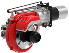
FBR produces over 870 catalogue products covering gas burners, diesel (light-oil) burners, heavy-oil burners, dual-fuel units, gas train configurations, and spare parts. The range spans single-stage units such as the X G oH 2001 c (SKU 001082) — a 90 W fan-motor light-oil burner rated 23.7–39.1 kW — through to large progressive/modulating heavy-oil burners like the FNDP 100/M TC SA (SKU 003099) rated up to 206 kg in weight and designed for sliding or fully modulating PID control. Low-NOx variants such as the FGP 100/2 TC EVO SI (SKU 001701) (NOx < 120 mg/kWh) and the GPL (SKU 002422_41) gas burner (NOx < 60 mg/kWh, Class 4) add emissions-compliance considerations to the maintenance programme.
Maintenance Interval Reference
The table below summarises recommended inspection and service intervals for FBR burner types. Always defer to the specific burner's documentation where available; the intervals below represent industry-standard best practice for the burner categories in FBR's range.
| Burner Category | Typical Power Range | Nozzle Check | Full Service | Combustion Analysis |
|---|---|---|---|---|
| Single-stage light-oil (e.g. SKU 001082, 001119) | 23.7–59.3 kW | Every 500 h or annually | Annually or every 1,000 h | At each service |
| Two-stage / Low-NOx light-oil (e.g. SKU 001701) | 333–1,186 kW | Every 500 h | Every 1,000 h | At each service + after any nozzle change |
| Progressive / modulating light-oil (e.g. SKU 001729) | Up to 150 kg unit weight | Every 500 h | Every 1,000 h | At each service + after actuator calibration |
| Heavy-oil two-stage (e.g. SKU 003137) | 380–1,542 kW | Every 500 h | Every 1,000 h | At each service; viscosity check quarterly |
| Heavy-oil modulating (e.g. SKU 003099) | Sliding / PID modulating | Every 500 h | Every 1,000 h | At each service; preheater check monthly |
| Gas burners single/two-stage (e.g. SKU 002707_31, 002422_41) | 11.6–850 kW | Inspect gas train annually | Annually or every 2,000 h | At each service + after gas train adjustment |
| Large modulating gas (e.g. GPL NO-CODE) | Up to 540 kg unit; nozzle DN495 | Inspect gas train every 1,000 h | Every 1,000 h | At each service + after actuator recalibration |
Routine Preventive Maintenance Checklist
Carry out the following tasks at every scheduled service. Tick each item before returning the burner to service.
- Nozzle inspection: Remove and inspect the nozzle for wear, clogging, or spray-pattern distortion. Check the spray angle stamped on the nozzle body against the original specification. Replace if worn — nozzles are a consumable item.
- Electrodes and ignition leads: Check electrode gap against the dimension marked on the burner head drawing. Look for carbon tracking on ceramic insulators. Replace cracked ceramics immediately.
- Flame detector / photocell: Clean the UV cell or photoresistor lens with a dry lint-free cloth. Verify the detector's signal output during a controlled test start.
- Air damper and fan: Inspect the fan impeller for dust build-up, especially on units with fan motors from 90 W (SKU 001082) to 2.2 kW (SKU 003137). Clean blades and verify damper movement is smooth and free of binding.
- Fuel filter / strainer: Clean or replace the fuel filter element. On heavy-oil burners, check the preheater element and thermostat; verify oil reaches the correct viscosity before the burner attempts ignition.
- Gas train components: On gas and dual-fuel burners, inspect valves, pressure regulators, and proving systems for leaks using an approved leak-detection fluid. Never use an open flame.
- Combustion analysis: Measure CO₂, O₂, CO, and flue-gas temperature with a calibrated analyser. Adjust air/fuel ratio to achieve clean combustion within the appliance's rated parameters.
- Control box / programmer: Check wiring terminals for corrosion or looseness. Verify lockout reset function operates correctly.
- Mechanical fixings: Inspect burner-to-boiler flange bolts, flexible hose connections, and cable glands for tightness and signs of heat damage.
Troubleshooting Common Faults
Work through each diagnostic sequence in order before replacing components. Many apparent component failures are caused by upstream conditions such as fuel supply pressure, air supply restriction, or incorrect control settings.
Fault 1 — Burner Locks Out on Start-Up (No Flame Established)
- Confirm fuel supply is open and supply pressure is within the range specified on the burner data plate.
- Check the ignition transformer output: listen for a spark during the ignition period. If absent, test transformer secondary voltage with an appropriate meter.
- Inspect electrode gap and condition. Re-gap or replace electrodes if worn or carbon-bridged.
- Verify the flame detector is clean and correctly seated. Substitute a known-good detector to isolate the component.
- On oil burners, confirm the nozzle is not blocked. Remove, clean, and flow-test or replace.
- On heavy-oil burners (e.g. FNDP series), confirm oil preheater has reached operating temperature before the start sequence initiates.
- Check the control box / programmer for correct wiring and that the safety lockout timer has not been shortened by a previous fault.
- Review the purge period setting — insufficient pre-purge can leave residual combustion products that prevent clean ignition.
Fault 2 — Unstable or Fluctuating Flame
- Check fuel supply pressure for fluctuation using a pressure gauge at the burner inlet; pressure drops during firing indicate an undersized supply line or failing pump.
- Inspect the air damper for binding or slipping actuator linkage, particularly on modulating units such as the FGP 130/M TL EVO SA (SKU 001729) or FNDP 100/M TC SA (SKU 003099).
- Clean the flame detector lens — a partially obscured detector causes intermittent flame-signal loss.
- Check for air ingress into the fuel line (oil burners): bleed the pump and inspect suction-side fittings.
- On gas burners, verify gas train valve operation and that the pressure regulator is not hunting.
- Inspect the combustion head for carbon deposits or distortion that may be disrupting the flame pattern.
Fault 3 — Sooting and Smoke Emission
- Perform a combustion analysis immediately. Excessive CO or black smoke indicates a rich mixture (insufficient air or excess fuel).
- Check the air damper setting and fan rotation direction — reversed motor phasing (3-phase units) halves airflow.
- Inspect and replace the nozzle if the spray angle or flow rate has degraded.
- On heavy-oil burners, verify oil viscosity at the nozzle by confirming preheater temperature is correct.
- Check the flue and heat exchanger for blockage restricting draught.
- On Low-NOx variants (FGP 100/2 TC EVO SI, GPL SKU 002422_41), verify that the recirculation or staged-air system is functioning — blockage here directly increases particulate emissions.
Fault 4 — Overheating / High Flue-Gas Temperature
- Check heat exchanger surfaces for scale or fouling — this is a boiler-side issue but manifests as a burner symptom.
- Verify the burner is not over-fired: confirm rated maximum output (e.g. 1,542 kW for SKU 003137) is not being exceeded by checking fuel flow rate.
- Inspect the combustion head geometry for damage that may be concentrating the flame.
- Review modulating actuator calibration on progressive/modulating burners to ensure high-fire position corresponds to the correct fuel and air settings.
Repair vs. Replace Decision Guide
- Replace (consumables): Nozzles, ignition electrodes, ignition leads, flame detector cells, fuel filter elements, and gaskets should be replaced at each service or when worn — repair is not cost-effective.
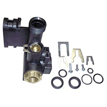
- Repair (mechanical): Fan motor bearings, damper linkages, and preheater elements can often be replaced in-situ using FBR spare parts (14 spare-part SKUs available to order from 3G Electric).
- Replace (control components): Control boxes and programmers that have suffered internal lockout faults or water ingress should be replaced rather than repaired — field repair of safety-critical electronics is not recommended.
- Replace (burner): When the combustion head shows thermal distortion, the burner body is cracked, or cumulative repair costs approach the cost of a new unit, replacement is the economical choice. Contact 3G Electric for a like-for-like or upgraded FBR replacement; lead time is confirmed at quotation.
Frequently Asked Questions
How often should FBR oil burner nozzles be replaced?
Replace nozzles at least annually or every 500 operating hours, whichever comes first. Nozzles are consumable items — worn spray geometry causes sooting, poor combustion efficiency, and increased emissions regardless of other burner condition.
What causes an FBR burner to lock out repeatedly on start-up?
Repeated lockout is most commonly caused by a dirty or failed flame detector, a worn or blocked nozzle, insufficient fuel supply pressure, or a faulty ignition transformer. Work through the Fault 1 diagnostic sequence above before replacing the control box.
Can FBR heavy-oil burners run on light oil as a backup?
No — heavy-oil burners such as the FNDP series are designed specifically for viscous fuels and include preheating systems sized for that fuel. Running them on light oil without OEM authorisation risks incorrect atomisation, combustion instability, and potential damage. Consult FBR documentation or 3G Electric for guidance.
How do I verify the correct electrode gap on an FBR burner?
The correct electrode gap is marked on the burner head assembly drawing supplied with the unit. Do not use a generic value — check the stamped or printed dimension on the head drawing, set the gap with a feeler gauge, and confirm a strong spark during a controlled test start.
What is the difference between two-stage and modulating FBR burners for maintenance purposes?
Two-stage burners switch between fixed low-fire and high-fire positions; maintenance focuses on the two fuel and air settings. Modulating burners (e.g. SKU 001729, SKU 003099) use actuators and PID control, requiring additional actuator linkage inspection, potentiometer checks, and combustion analysis at multiple firing rates during each service.
Are FBR spare parts available for older burner models?
3G Electric carries FBR spare parts available to order across the product range. Lead time is confirmed at quotation. Provide the burner model number and serial number when enquiring to ensure correct part identification.
How do I reduce NOx emissions from an FBR Low-NOx burner that is exceeding limits?
First perform a full combustion analysis to verify air/fuel ratio. Check that the staged-air or flue-gas recirculation system is unobstructed and functioning. Verify the burner is operating within its rated power range — Low-NOx performance (e.g. < 60 mg/kWh for SKU 002422_41) is only guaranteed within the specified firing envelope.
When should I call a specialist instead of troubleshooting an FBR burner myself?
Engage a qualified combustion engineer when: the gas train requires pressure testing or valve replacement, the control box requires internal repair, combustion analysis shows CO above safe thresholds, or the burner has suffered a fuel spill or fire event. Safety-critical work must not be performed by unqualified personnel.